Purpose
The instrumentation system includes all of the sensors on the test stand and motor which output electrical signals (usually analog) based on the readings of physical values. The instruments are chosen to provide meaningful and comprehensive data on the motors operation and performance.
The data acquisition system (DAQ) is the system responsible for reading the analog signals from the instrumentation system, and converting them to a digital signal and storing them on a long term storage device. A DAQ should also be able to be controlled manually, and record timestamps to correspond with the readings from the instrumentation.
DAQ
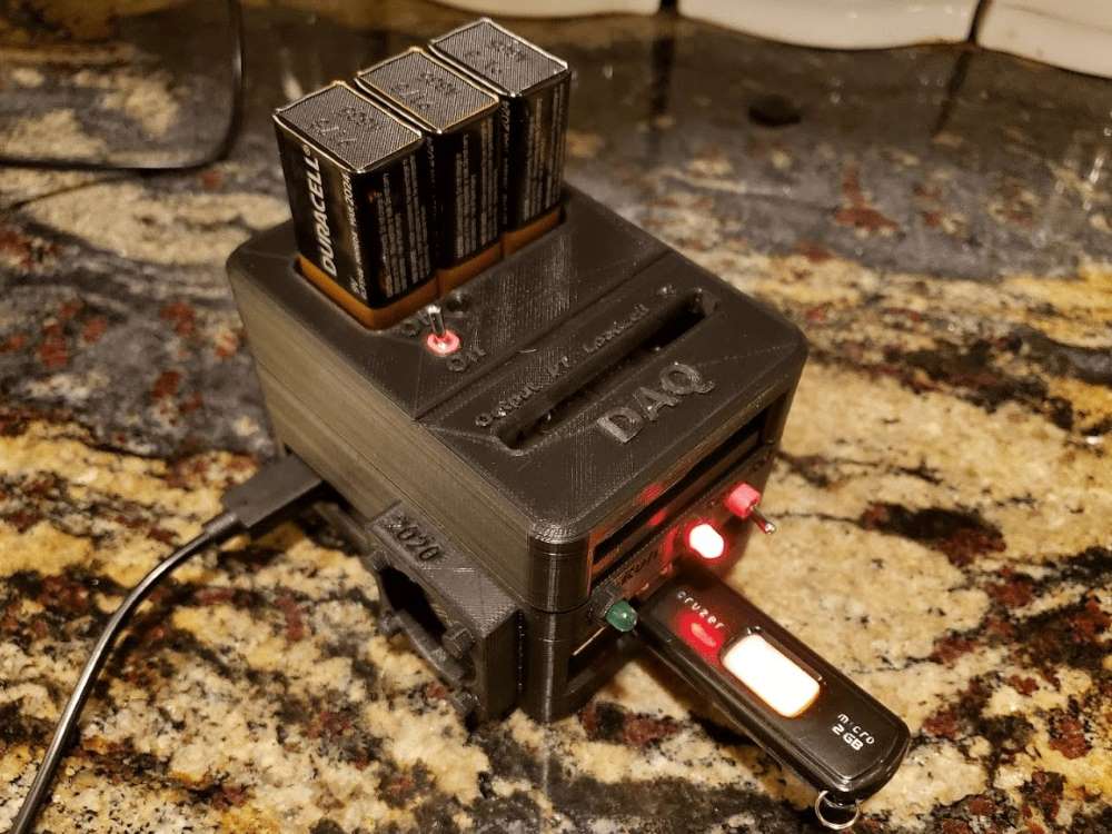
The DAQ constructed for our test stand is shown below. The left picture shows the electronics of the system, and the picture on the right shows the functioning unit in its 3d-printed enclosure.
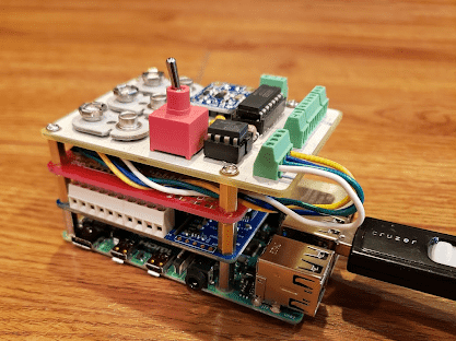
In the figures above on the left, the major electronic components of the DAQ system can be seen. The bottom layer is a Raspberry Pi. The Raspberry Pi is responsible for converting voltages to physical values, storing data, controlling the mode of the system, managing errors, and signaling to the user its state. The blue board above the Raspberry Pi is the MCC 118 DAQ HAT. This is a DAQ module specifically designed for the Raspberry Pi. It collects analog voltage signals from the instrumentation at a specified rate, and sends the data to the Raspberry Pi in chunks. The white board on the top of the stack is a custom printed circuit board to convert the signals from the various instruments to properly scaled, analog voltage signals for the MCC 118 DAQ to read.
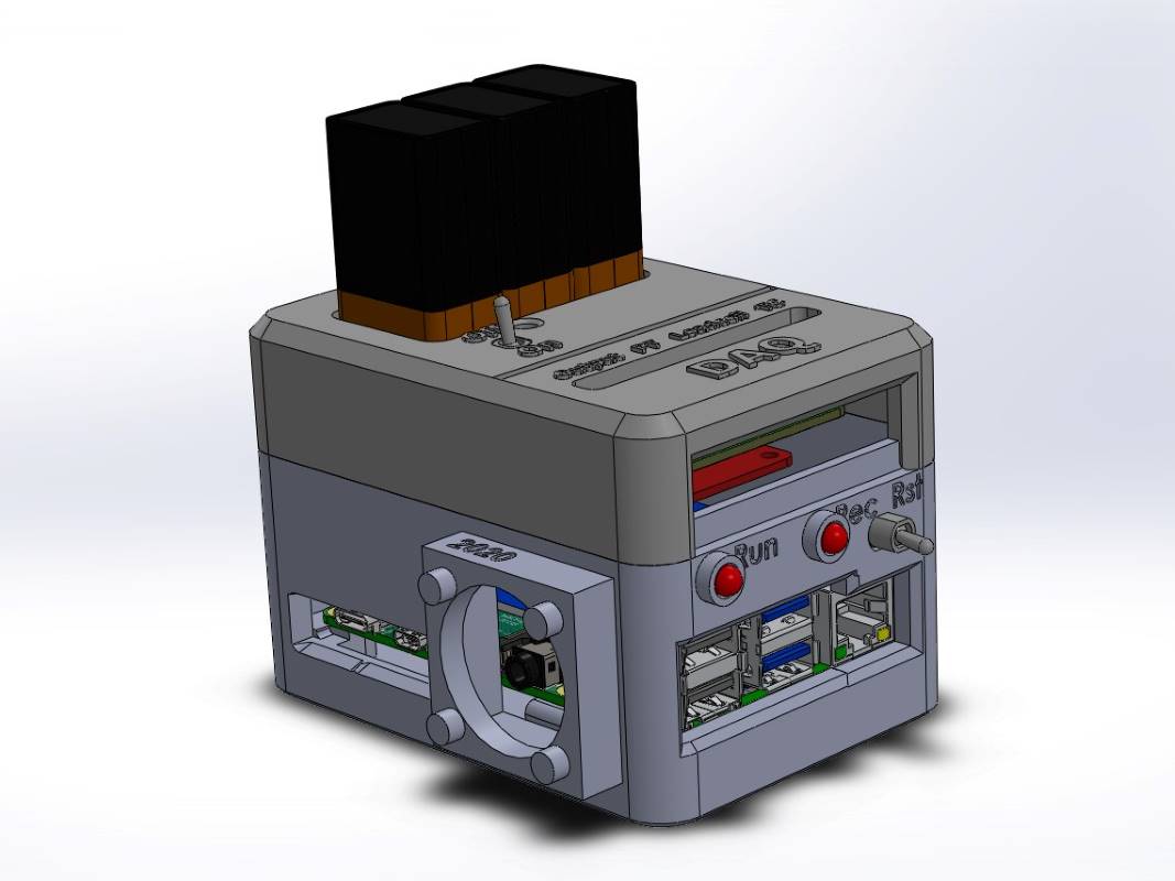
On the right is a casing for the DAQ system. This casing serves to protect the DAQ, hold switches and lights, allow access to necessary ports, and house a fan. Multiple switches can be seen on the box, these are for controlling the state of the DAQ (record data, reset) and allowing power to the system. The lights on the system are to indicate in real time whether the system is on, and whether it is properly recording data.
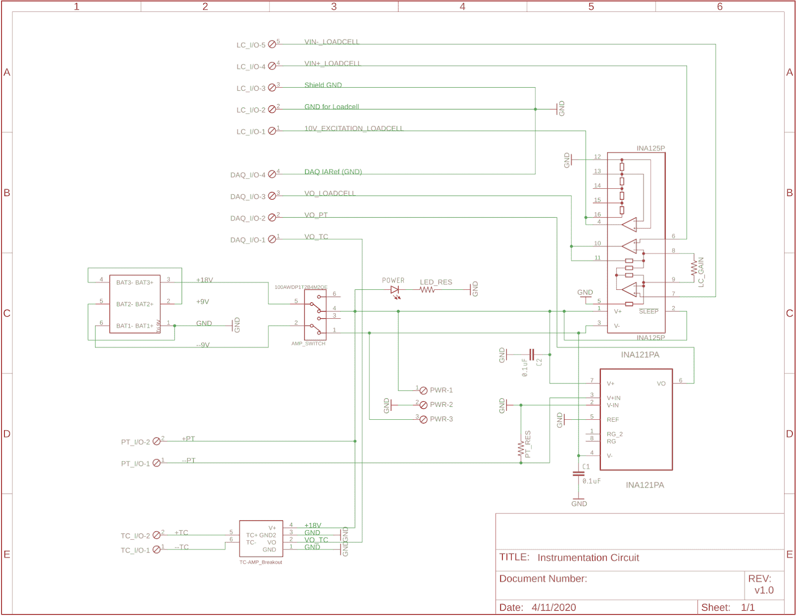
The schematic for the white PCB is shown below. This must convert signals from three instruments, a load cell, a pressure transducer and a thermocouple, to scaled analog voltages. The load cell has a wheatstone bridge which correspondingly outputs a very small voltage. It also must be powered by a constant, clean voltage. Both of these functions are performed by the INA125P chip. This chip outputs a constant voltage to the sensor, and also provides a large amplification from the signal it receives to be fed to the DAQ in an appropriate range. Since the calibration of the load cell changes frequently, a calibration program has been made on the Raspberry Pi to allow quick calibration. The pressure transducer outputs a 4-20mA signal corresponding to 0-1500 psi. Running this current across an accurate 250 ohm resistor would make the voltage across the resistor 1-5V. This voltage is then run through an INA 121 differential amplifier to isolate signals and reduce grounding errors (the DAQ reads single ended voltages only). Finally, the thermocouple is run through a breakout board which converts the temperature to a voltage. The output of all these amplifiers can then be sent to the DAQ to get recorded by the Raspberry pi.