Purpose
The goal of a thrust stand is to provide a robust platform for testing and collecting data from rocket motors. Our thrust stand collects force, pressure,
and temperature measurements which are fed electrically to the data acquisition box. Testing is an important part of motor development as it allows propellant
grain geometry and composition to be optimized. Testing also allows for validation of theoretical predictions.
Thrust Stand Parts:
-Frame
-Load cell
-Pressure transducer
-Thermocouple
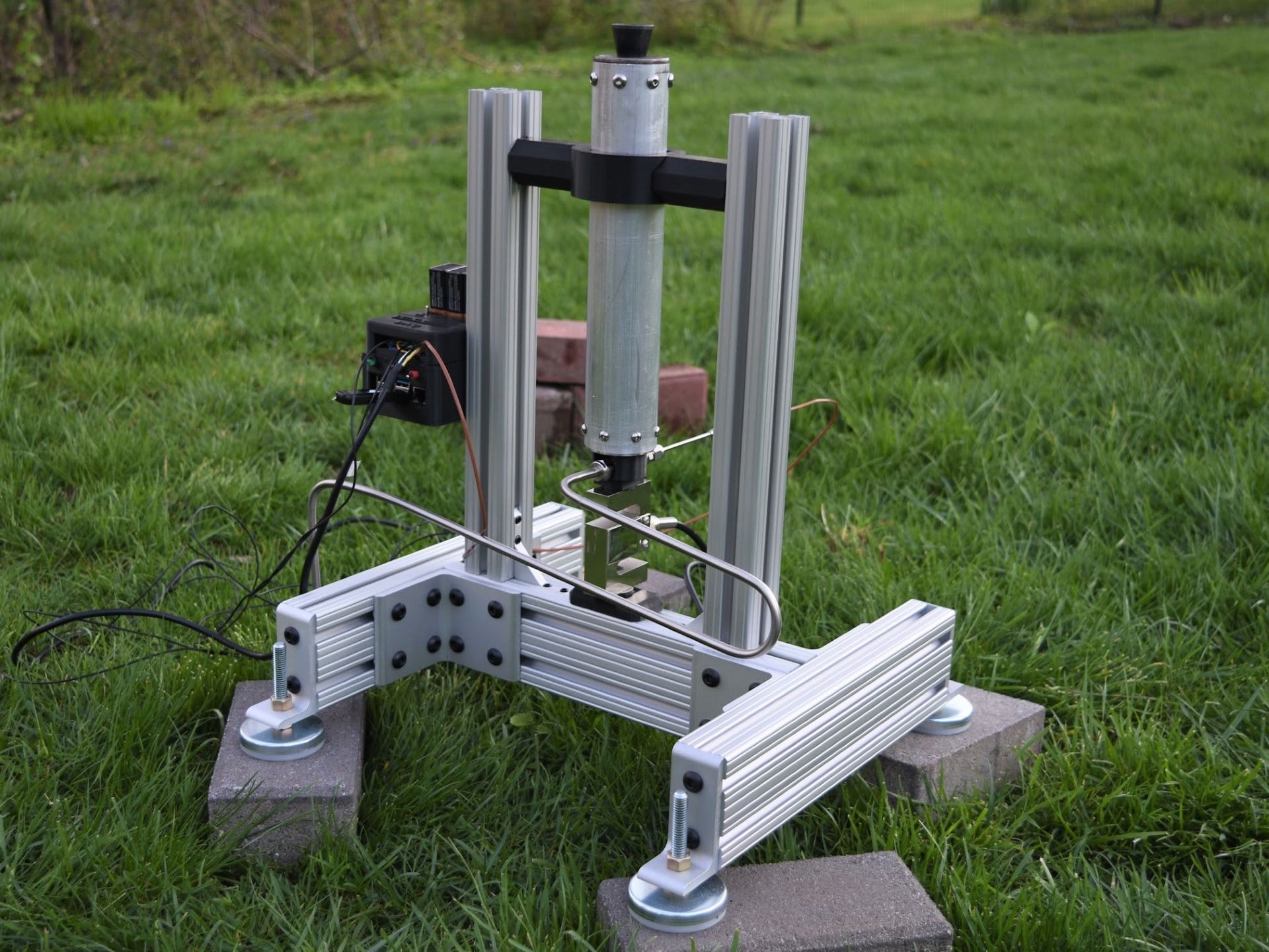
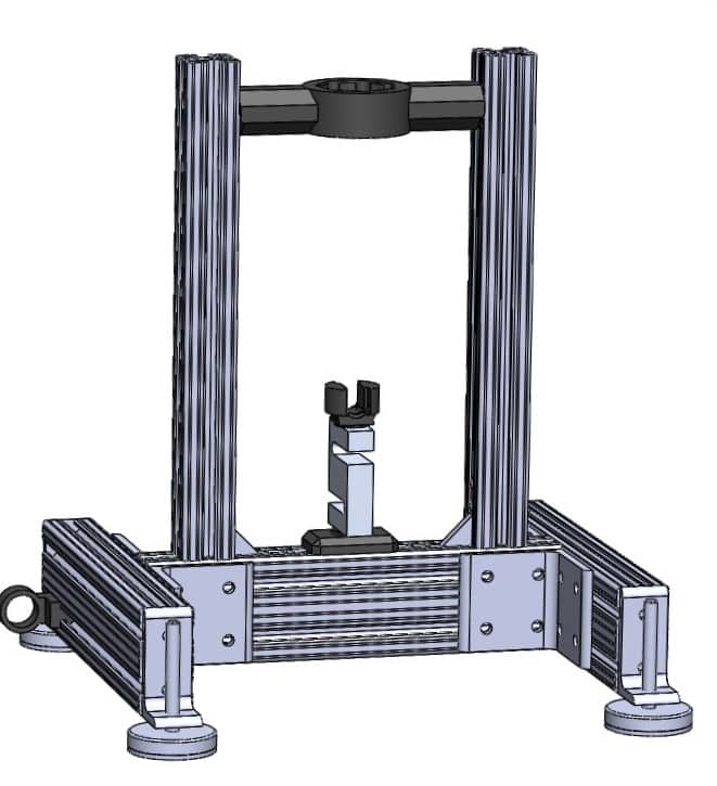
Frame:
The goal of the frame is to hold the motor securely and provide mounting locations for sensors. The frame was made largely of aluminum extrusion for its ease of use and affordability. One key feature of the thrust stand is the motor’s vertical configuration with the thrust vector pointed toward the ground (flamey end up). This eliminates the need for heavy ballasts to anchor the stand.
3D prints were used for holding the top of the motor, and for mounting sensors to the frame. Weight was not a large design factor because the stand is stationary and relatively small. To determine if the thrust stand could support the expected forces (~200lbf max), hand calculations and an Ansys static structural study were performed.

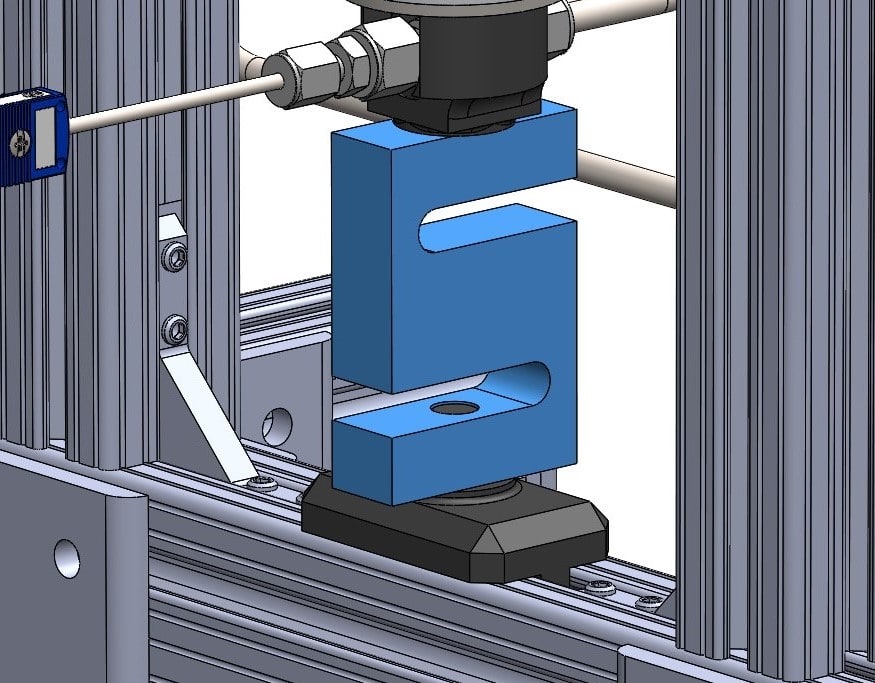
Load Cell:
The load cell is used to measure the force in the vertical direction exerted by the motor. By measuring force and time we are able to derive the impulse of the motor. The load cell is connected to the motor and frame using 3D print adapters.
Pressure Transducer:
The pressure transducer converts pressure from hot combustion gasses into an electrical signal that can be recorded. Chamber pressure is an important data point as it is directly related to thrust of the motor and burn rate of the propellant surfaces.
The pressure transducer is routed to the chamber through a 1m stainless steel tube used to dissipate heat and protect the sensor from the hot combustion gasses.
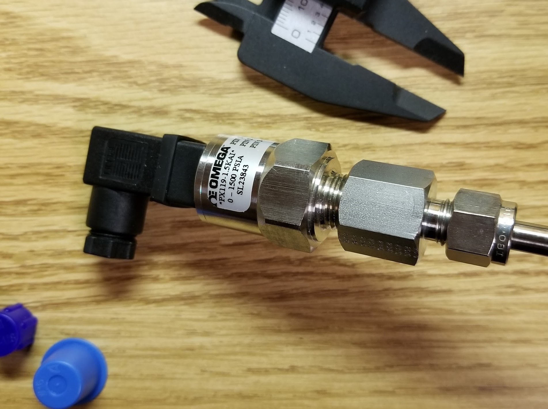
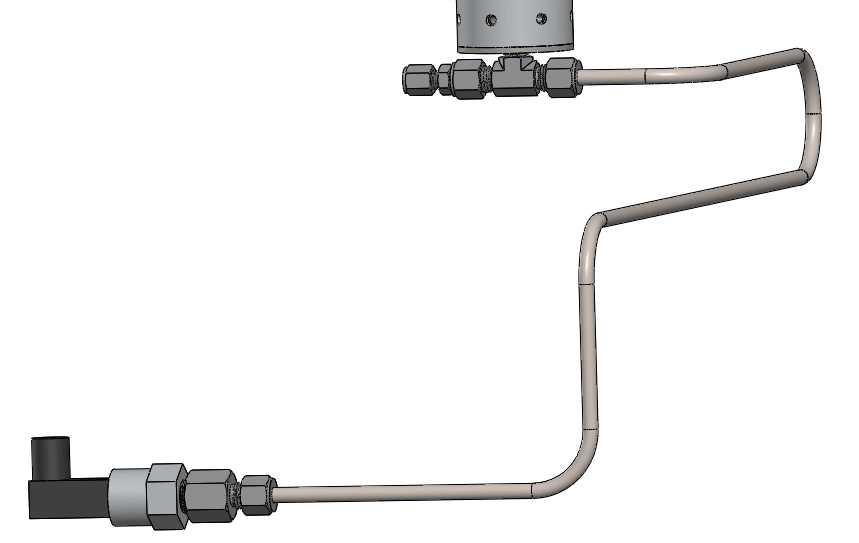
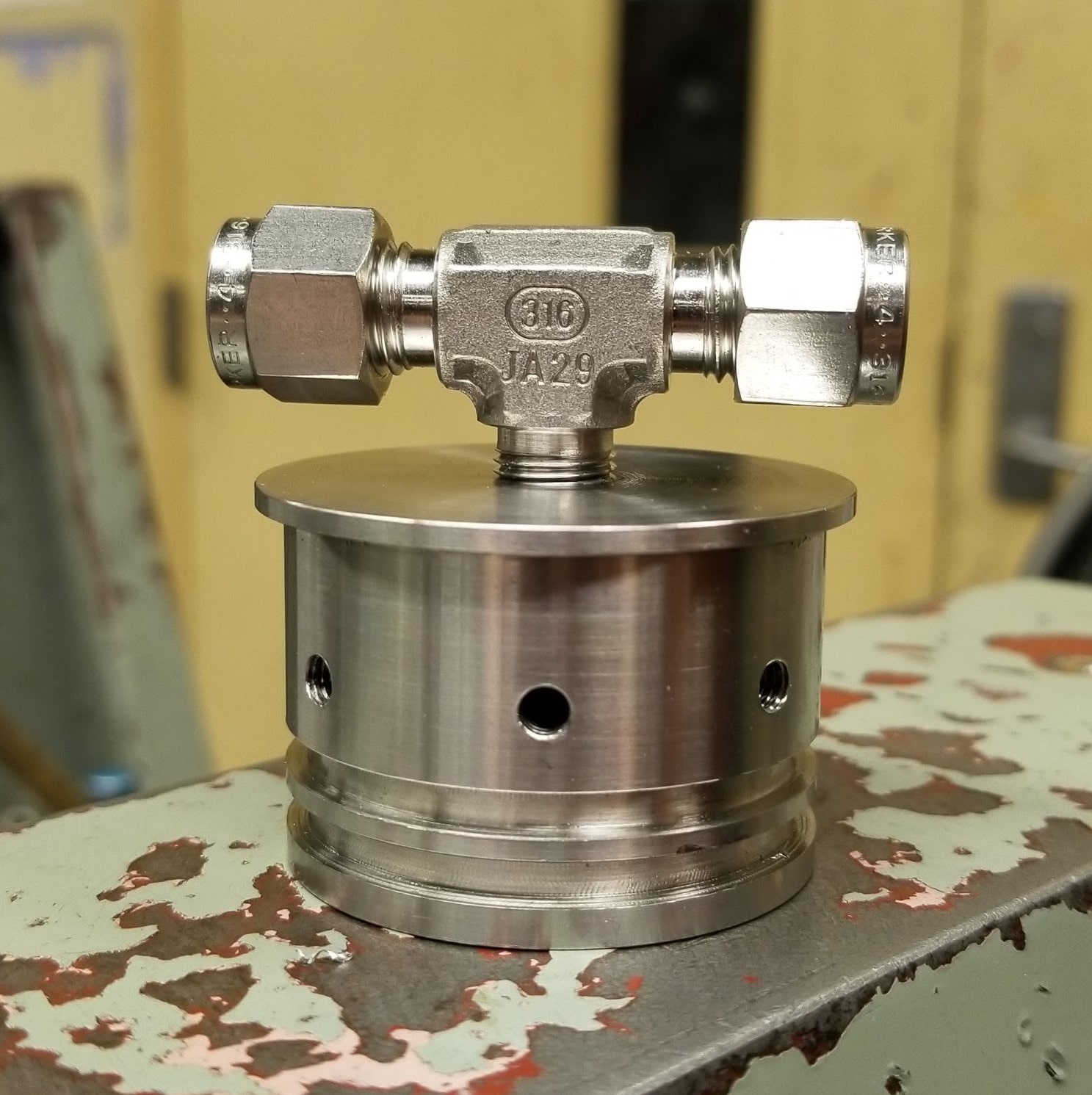
A new bulkhead was machined with a port for the pressure transducer and thermocouple. A tee screws into this port and splits off for the tube and pressure transducer to connect to.
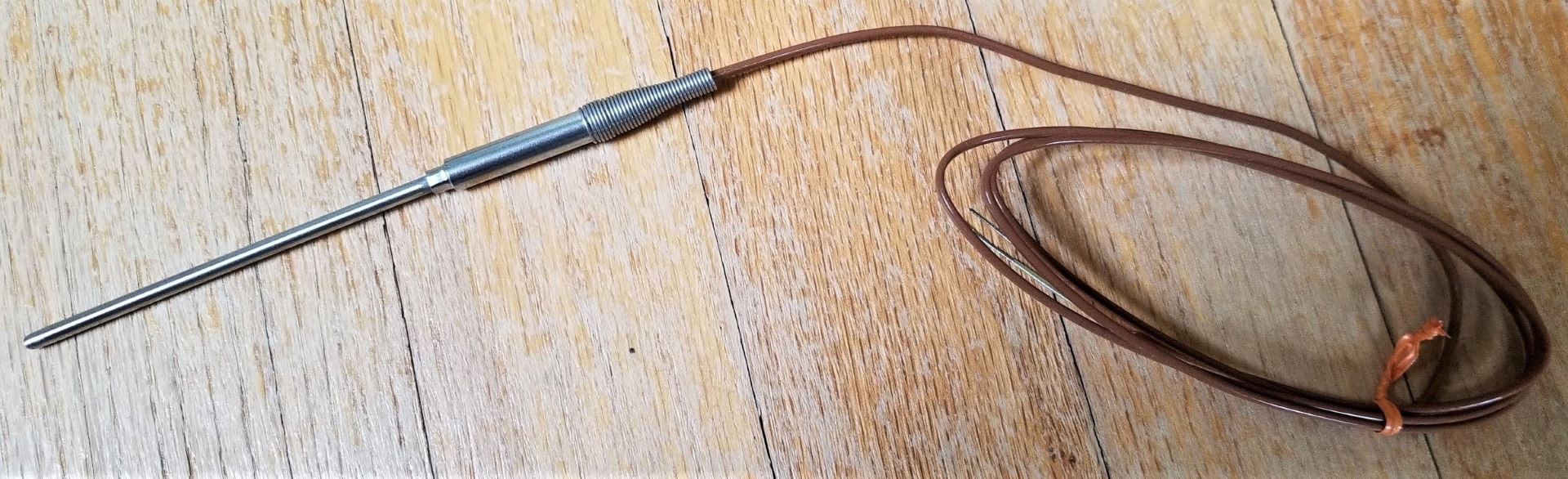
Thermocouple:
The thermocouple is used to measure the temperature of motor combustion gasses. A K-type thermocouple was chosen for its low cost and wide recording range (−200 °C to +1350 °C). Probe diameter affects response time, so a 0.125in probe was chosen to be fast enough for motor temperature variations. The thermocouple mounts into the bulkhead in a similar way to the pressure transducer, and produces a voltage due to the thermoelectric effect. This tiny voltage is read by the data acquisition box.